


For permanently installed solar repeaters at hard-to-reach locations.
The Inhero MR2 combines LoRa radio for MeshCore with power management for off-grid solar operation. It lets you monitor battery reserves remotely, offers configurable charging behaviour in freezing conditions and automatically resumes operation after a low-voltage pause once the battery has recovered sufficiently.
- Automatic recovery: Low-voltage sleep with consumption below 500 µA, an active charging path and hourly voltage checks.
- Configurable charging in freezing conditions: Temperature-dependent charging for Li-ion and LiFePO₄; optional JEITA override for experienced operators at a maximum of 0.05C. This disables both cold and hot charging cut-offs — see details below.
- Flexible power supply: MPPT solar input from 3.6–24 V, maximum open-circuit voltage of 25 V; support for Li-ion 1S, LiFePO₄ 1S, LTO 2S and Na-ion 1S.
- Check energy reserves remotely: Charge and discharge balance over 24 hours, 3 days and 7 days, plus an estimated remaining runtime calculated from these figures.
- For compact installations: 45 × 40 mm, integrated environmental sensor and USB-C for setup and firmware updates.
Before you buy: The MR2 is a board with connection accessories for a self-assembled installation. Add a battery, solar panel, LoRa antenna and enclosure to suit your application. MeshCore builds are available to download; you install the application firmware yourself. Meshtastic is not currently supported.
When the battery runs low: pause, recharge, restart automatically
During a sustained energy shortage, the MR2 shuts down radio operation in a controlled way and enters low-voltage sleep. Current consumption drops below 500 µA. The solar charging path remains active, allowing the battery to recover when sufficient solar energy is available and charging is permitted.
The board checks its battery voltage once an hour. If the recovery threshold for the selected battery chemistry has been reached, it starts automatically. Otherwise, it returns to sleep. A 200 mV gap between the sleep and recovery thresholds helps prevent repeated restarts when the battery voltage is marginal.
For remote locations, this means: After a low-voltage pause, the repeater can resume operation without a manual reset. The repeater does not operate while asleep.
Make use of winter charging opportunities
With the factory settings, the MR2 monitors battery temperature via an NTC for Li-ion and LiFePO₄. The fmax setting allows a proportion of the configured charging current in the range of approximately −2 to +3 °C. Charging remains blocked below approximately −2 °C. With sufficient solar power, the repeater can also run directly from solar while battery charging is blocked.
With jeitaignore, experienced operators can also use charging opportunities at lower freezing temperatures. The optional override only takes effect if battery capacity has been explicitly configured and the configured maximum charging current is no greater than 0.05C of that capacity. For example, with batcap = 9,000 mAh, the maximum permitted setting is 450 mA. This suits installations with small solar panels and large battery reserves.
The override is disabled by default. It disables both the charger's cold and hot charging cut-offs. The 0.05C limit caps the charging current. Charging in freezing conditions can cause permanent capacity loss and cell damage even within this limit. Use is at your own risk, taking the specific cell and site conditions into account.
Freezing-temperature charging and cell selection in the Battery Guide · How fmax and jeitaignore interact
Assess energy reserves remotely
The MR2 measures the charge and discharge balance over 24 hours, 3 days and 7 days. Through admin access in the MeshCore app, you can see whether an energy deficit is developing. The remaining runtime estimate takes into account both the recent deficit and the battery reserve expected to be usable in cold conditions.
Measured consumption: 0.98 Wh per day in a 24-hour test with typical repeater radio traffic. Your actual requirements depend on factors including radio traffic. Size the panel and battery to suit the location, orientation, shading and desired time without sufficient solar input.
View measurements and technical documentation
Which version suits your battery?
1S denotes the voltage of a single cell; 2S denotes two cells connected in series.
| Version | Suitable for |
|---|---|
| Battery cable with open ends | Custom battery configurations where you select and assemble the cell, temperature sensor and required protection circuitry yourself. |
| Battery cable with LiFePO4 protection module | LiFePO₄ batteries in a 1S configuration. The protection module and matching temperature sensor are already soldered and tested. |
| Battery cable with Li-ion protection module | Li-ion and LiPo batteries in a 1S configuration. The protection module and matching temperature sensor are already soldered and tested. |
The protection modules protect the battery against overvoltage and undervoltage. They do not provide reverse-polarity protection for the board.
The battery cable is already prepared for both versions with a protection module. Before charging, configure the battery chemistry, capacity and charging current for your battery as described in the Quick Start guide. The protection modules do not replace this configuration. Connect the battery as described in the Quick Start guide.
LTO 2S requires an external balancer. LTO and Na-ion operate without the temperature-dependent charging supervision used for the Li-ion/LiFePO₄ configurations; observe the permitted charging temperatures in the relevant cell datasheet.
What's included
- 1 × Inhero MR2 board, hardware revision 1.1
- Short connection cables with open ends and JST sockets on the board side
- 1 × solar connection cable, JST-PH 2.0, 2-pin, 20 cm
- 1 × battery connection cable, JST-PH 2.0, 3-pin, 20 cm, in the selected version
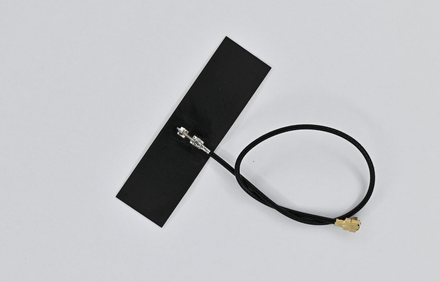
- 1 × adhesive BLE antenna, 2.4 GHz, U.FL, 10 cm
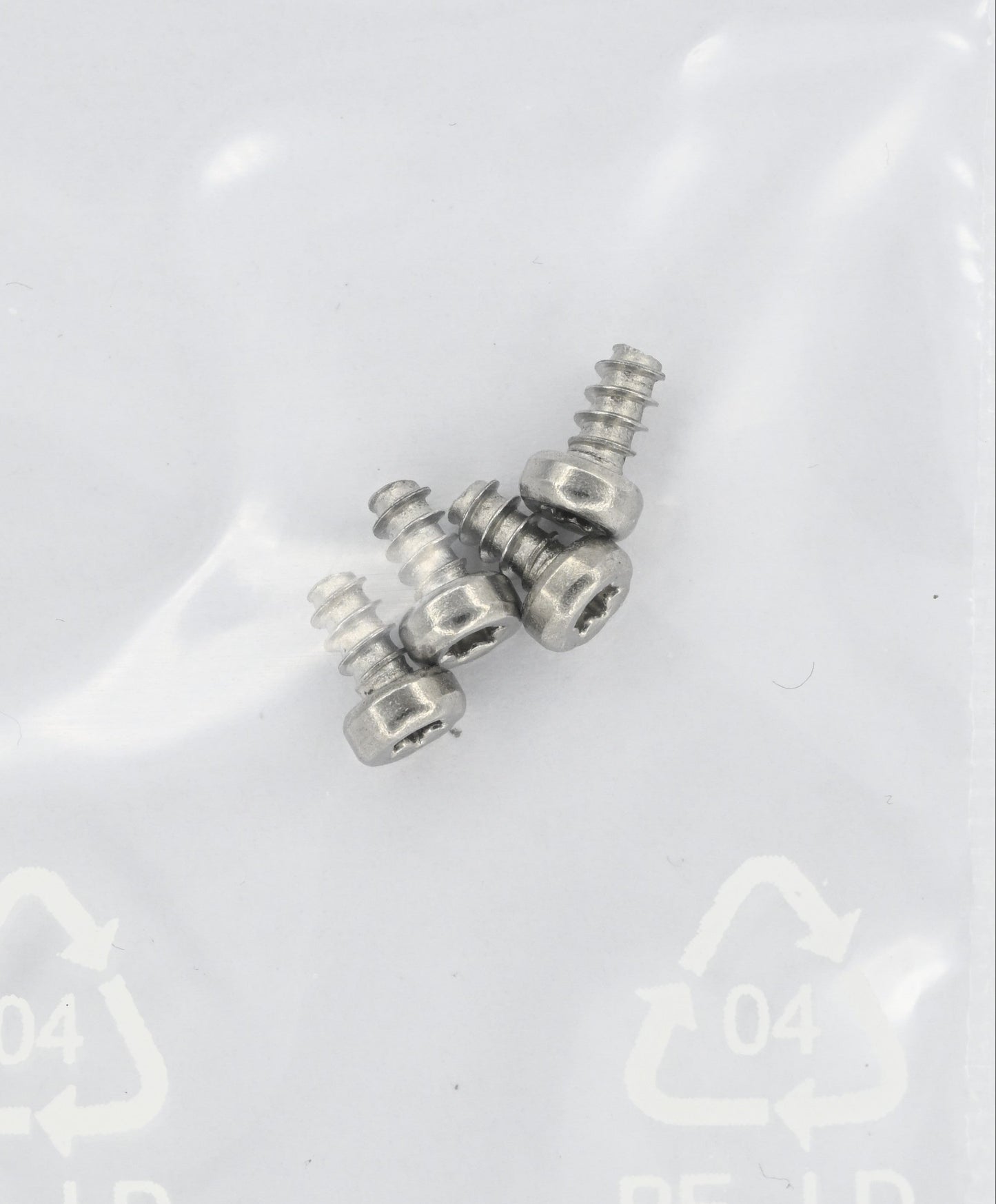
- 4 × A2 stainless steel mounting screws, Ø 2.5 × 4.5 mm, T8
Also required: A suitable battery, solar panel, LoRa antenna and, for outdoor use, a suitable enclosure. The included BLE antenna is exclusively for 2.4 GHz service access and does not replace a LoRa antenna.
Solar and battery accessories · LoRa antennas · Enclosures and kits
Set up MeshCore
The MR2 ships with the OTAFIX bootloader. No application firmware is preinstalled. Ready-to-use MR2 builds for MeshCore and Quick Start guides in German and English are available to download.
To install the firmware, connect the board to your computer using a USB-C data cable and press the reset button twice in quick succession. Then copy the appropriate .uf2 file to the USB drive that appears. No programming adapter is required.
Configure the battery chemistry, capacity and charging current for your battery using the Quick Start guide. The state-of-charge display also requires an initial full charge as a reference. Read the safety instructions below before connecting and operating the board.
Firmware compatibility: Use the linked MR2 builds. Inclusion in the official MeshCore project is being prepared. Meshtastic support is planned but is not currently available.
Download MeshCore firmware and Quick Start guides
Technical specifications at a glance
| Feature | Specification |
|---|---|
| Radio module | RAK4630(H), nRF52840 + SX1262 |
| Solar charge controller | BQ25798, buck/boost with MPPT |
| Solar input | 3.6–24 V; maximum open-circuit voltage of 25 V |
| USB | USB-C, 5 V; shared charging input with solar |
| Battery chemistries | Li-ion 1S, LiFePO₄ 1S, LTO 2S, Na-ion 1S |
| Charging current | 50–1500 mA, configurable via CLI |
| Battery monitoring | INA228 coulomb counter |
| Environmental sensor / real-time clock | BME280 / RV-3028-C7 |
| Voltage regulator | TPS62840, 3.3 V |
| Measured repeater power consumption | 12.3 mA at 3.3 V; 0.98 Wh/day with typical radio traffic |
| Quiescent current, active idle | 6.0 mA at 4.2 V battery voltage / 7.7 mA at 3.3 V battery voltage |
| Deep sleep | Below 500 µA; charging path remains active |
| Connections | USB-C, 2 × U.FL, solar JST-PH 2.0 2-pin, battery JST-PH 2.0 3-pin with NTC |
| Dimensions / mounting | 45 × 40 mm / four M2.5 mounting holes |
The installed high-band radio module supports IN865, EU868, US915, AU915, KR920 and AS923-1/2/3/4 at the hardware level. 433 MHz and 470 MHz are not supported. Hardware support does not mean approval for every country of use; see the compliance information.
Energy monitoring and remote administration in detail
The INA228 determines state of charge through coulomb counting. This requires a correctly configured battery capacity and an initial full charge as a reference. The remaining runtime estimate is based on the average daily deficit over the previous seven days; it is not a guarantee of future runtime.
After low-voltage sleep, SOC initially starts at 0% because charge is not counted during sleep. It synchronises to 100% at the next full charge. Energy statistics start over after every restart; a remaining runtime estimate requires at least 24 hours of valid data and a measured energy deficit.
Configuration and queries are available locally via USB serial or remotely through admin access in the MeshCore app. Commands include:
set board.bat: set battery chemistryset board.batcap: configure battery capacityset board.imax: set maximum charging currentset board.fmax: set the charging current proportion in the T-Cool range when JEITA is activeget board.jeitaignore: check the effective override state and any unmet prerequisitesget board.telem: retrieve battery and solar readingsget board.stats: retrieve the energy balance and remaining runtime estimateget board.selftest: test board components
Charging in freezing conditions in detail
Three charging behaviours are available for Li-ion and LiFePO₄. The temperatures refer to the documented MR2 thresholds and are approximate.
| Configuration | Approx. −2 to +3 °C | Below approx. −2 °C |
|---|---|---|
| Factory settings: JEITA active, fmax 0% | Charging blocked | Charging blocked |
| JEITA active, fmax 20 / 40 / 100% | Selected proportion of imax | Charging blocked |
| jeitaignore effectively active | Up to the configured imax, maximum 0.05C | Up to the configured imax, maximum 0.05C |
The override depends on the configured current limit, not the current the panel is supplying at that moment. A small panel therefore does not replace the correct configuration of batcap and imax.
set board.jeitaignore 1 saves the request for an override. The firmware checks whether it can take effect based on capacity and the current limit. If the prerequisites are no longer met, it becomes inactive; when they are met again, it automatically becomes active again. The setting persists across restarts and is re-evaluated after the battery configuration has been applied. get board.jeitaignore shows the state.
While the override is active, fmax does not apply. With set board.jeitaignore 0, the saved fmax behaviour applies again. LTO and Na-ion already operate without JEITA; their permitted charging temperatures are determined by the cell datasheet.
The charger continues to operate independently during low-voltage sleep. There is no replacement firmware monitoring for the cold and hot limits disabled by an active override.
Low-voltage sleep in detail
The INA228 signals an interrupt when voltage falls below the configured threshold for the selected chemistry; the firmware then initiates sleep. The RTC triggers a brief voltage check every 60 minutes. A full boot only occurs once the voltage is sufficient.
| Battery chemistry | Sleep below | Recovery from |
|---|---|---|
| Li-ion 1S | 3.10 V | 3.30 V |
| LiFePO₄ 1S | 2.70 V | 2.90 V |
| LTO 2S | 3.90 V | 4.10 V |
| Na-ion 1S | 2.50 V | 2.70 V |
Sleep leaves a residual current draw and does not replace suitable battery protection circuitry. After a very long period without charging, battery voltage may continue to fall.
⚠ Important safety instructions
- No reverse-polarity protection: The board has no hardware reverse-polarity protection on the battery or solar input. Connecting with reversed polarity causes immediate, irreversible damage. Always check polarity before connecting.
- Observe cell chemistry: The cut-off thresholds for LiFePO₄ and Li-ion are not compatible. Select the battery cable version that matches your cell.
- NTC for temperature-monitored charging: For Li-ion and LiFePO₄, connect a suitable NTC or close the solder bridge for the onboard NTC. Without an NTC, active JEITA monitoring blocks charging. An effective
jeitaignoreoverride also removes this block but does not replace temperature monitoring; observe the effects on cold and heat protection described above. - Do not short-circuit the solar input while USB is connected: Both share the same input via a Schottky diode.
- LTO 2S: An external balancer is required for continuous operation; the board does not balance cells.
- ESD-sensitive assembly — handle only with suitable ESD protection.
- Always connect an antenna when operating the LoRa/BLE transceivers.
Compliance (RED 2014/53/EU)
The hardware has been tested by an accredited laboratory for compliance with the EU Radio Equipment Directive (RED 2014/53/EU) and is CE compliant. The final transmission characteristics (transmit power, frequency, duty cycle) depend on the firmware installed by the user and the selected antenna. The operator must coordinate transmit power and antenna gain to comply with the applicable EU limits (EN 300 220, ERC/REC 70-03).
The EU Declaration of Conformity covers operation within the EU; radiated power certification was performed with the 863–870 MHz reference antenna. For the other bands supported at the hardware level by the installed (H) module, the relevant national radio regulations apply — frequency plan, radiated power and duty cycle or dwell time. Compliance, including any locally required approval, is the responsibility of the integrator or user. → Regulatory notes in the documentation
Radio module approvals: The installed RAK4630 has modular FCC approval under FCC 15.212 (2AF6B-RAK4630) and Canadian ISED certification under RSS-247, Issue 2 (25908-RAK4630). These approvals apply to the module, not the MR2 — no FCC or ISED approval is declared for the board itself. No compliance is declared for Australia; the MR2 does not carry the RCM mark. Annex A of the ISED certificate lists a 3.0 dBi dipole as the tested LoRa antenna: using an antenna with higher gain falls outside the tested configuration, and assessment is then the operator's responsibility. Within the EU, the ERP limits stated above apply instead. → Full overview in the datasheet
Manufacturer (information pursuant to EU General Product Safety Regulation 2023/988)
Inhero GmbH, Gewerbestraße 19, 08115 Lichtentanne, Germany
Email: info@inhero.de
Product identification: Inhero MR2, hardware rev. 1.1