


Inhero MR2 – Solar Mesh Repeater Board
- Supports Li-ion, LiFePO₄, lithium titanate (LTO) and Na-ion batteries, including low-temperature charge-current limiting
- INA228 coulomb counting provides measured SOC values (essential for LiFePO₄) and remaining-runtime forecasts for periods of bad weather
- Auto sleep/wake-up on undervoltage to prevent brown-outs
- Universal solar input 3.6–24 V, automatic panel voltage detection, buck/boost, MPPT
- BME280 environmental sensor and RV-3028-C7 RTC on board
- Quiescent current: 6.0 mA at 4.2 Vbat / 7.7 mA at 3.3 Vbat
- 0.98 Wh energy consumption per day in real repeater operation (24-hour measurement)
- Built for winter operation: measured energy balance over 24 h, 3 and 7 days plus a remaining-runtime forecast straight from the board
- Firmware: currently MeshCore only (ready-made builds available) – Meshtastic support is planned but not yet available
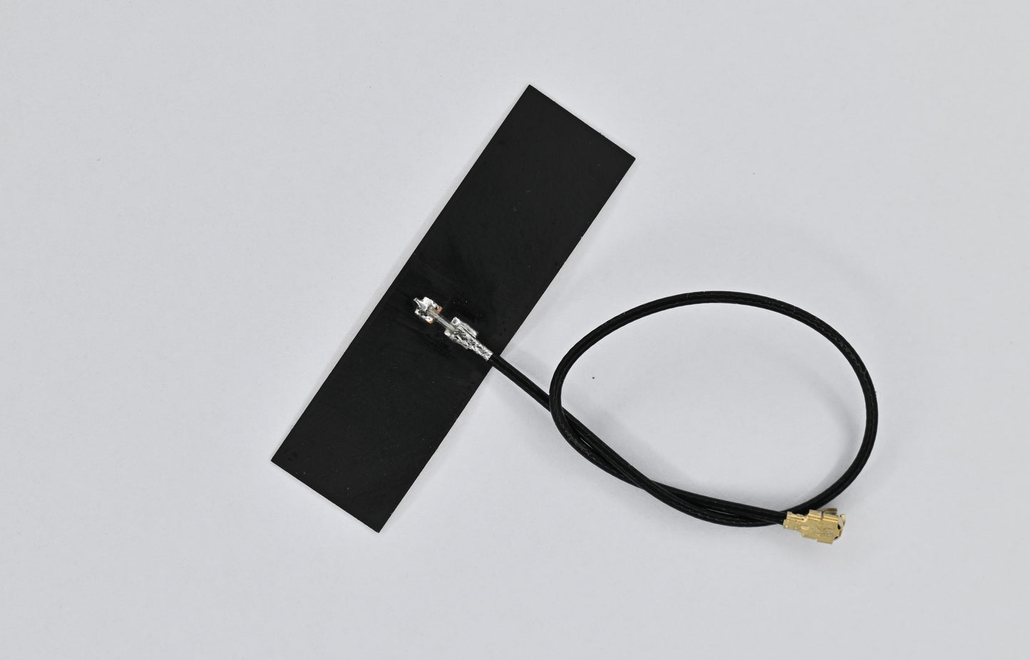
- Always included: solar connection cable, battery cable, mounting screws and BLE adhesive antenna
- CE-certified
MeshCore CLI
All board parameters are accessible at runtime via the MeshCore CLI – locally over USB serial, or remotely through the MeshCore app's admin access, without physical access to the device.
set board.bat | Cell chemistry: lifepo1s | liion1s | lto2s | naion1s | none |
set board.batcap | Nominal capacity in mAh (100–100000) |
set board.imax | Max. charge current in mA (50–1500) |
set board.fmax | Low-temperature charge-current limiting: 0% | 20% | 40% | 100% |
set board.mppt | MPPT on/off |
set board.leds | Board LEDs off |
set board.tccal | Calibrate battery temperature sensor (NTC) against BME280 |
get board.conf | B:lifepo1s F:20% M:1 I:500mA Vco:3.50 V0:2.90 |
get board.telem | B:3.34V/248.6mA/14C SOC:78.5% S:6.12V/162mA |
get board.cinfo | PG / CC |
get board.selftest | INA:OK BQ:OK RTC:OK BME:OK |
get board.stats | -24/-18/-15mAh C:280 D:304 3C:295 3D:313 7C:271 7D:286 BAT M:41% T:14d3h |
Example outputs are shown on the right. get board.stats returns the energy balance over 24 h, 3 and 7 days from the INA228 coulomb counter; T: is the remaining runtime until cutoff, calculated from the 7-day average of the daily deficit.
Description
The Inhero MR2 is a LoRa mesh repeater board based on the RAK4630 (nRF52840 + SX1262) with an integrated solar charge controller – usually referred to as a solar node or solar repeater in the community. It is populated with a BQ25798 buck/boost charge controller with MPPT and JEITA temperature management, an INA228 coulomb counter, an RV-3028-C7 real-time clock, a BME280 for temperature, humidity and barometric pressure, and a TPS62840 step-down converter for the 3.3 V rail. Connectors: two U.FL sockets for LoRa and BLE, USB-C for service and firmware updates, JST-PH 2.0 for battery (3-pin with NTC) and solar (2-pin). Dimensions 45 × 40 mm, four M2.5 mounting holes.
The solar input accepts 3.6 to 24 V with a maximum open-circuit voltage of 25 V. The MPPT operates autonomously; no adjustment to the panel voltage is required. Buck/boost charging works even when the panel voltage is below the battery voltage. Consumption in repeater operation averages 12.3 mA at 3.3 V, measured over 24 hours with typical radio traffic; that corresponds to 295 mAh or 0.98 Wh per day. At full duty cycle under EU868 g3 the calculated figures are 19.8 mA and 1.57 Wh/day. In Central Europe, 2 Wp with vertical south-facing mounting and no shading is reliably sufficient; built-up or partially shaded sites require 3–5 Wp. Some MR2 units even run year-round on 1 Wp at exposed, vertically south-facing locations.
Winter operation
Panel sizing is decided by winter, not by summer: irradiation in December in Central Europe is roughly an order of magnitude below the June average. That is precisely why the MR2 measures its energy balance instead of estimating it. get board.stats returns charge and discharge balance over 24 hours, 3 and 7 days, plus a remaining-runtime forecast from the 7-day average of the daily deficit. A shortfall becomes visible before the node goes down – and remotely, through the MeshCore app's admin access, without having to visit the site. In freezing conditions the charge controller limits the charge current via the NTC or blocks it entirely; the repeater itself keeps running on solar.
The battery chemistry is set once during installation via the CLI (set board.bat) and defines the charge cutoff and sleep voltages. If the battery voltage drops below the chemistry-specific threshold, the INA228 triggers a hardware interrupt. The board enters a deep sleep below 500 µA; the charge path remains active, and the real-time clock wakes the board hourly to check the voltage. Restart only occurs 200 mV above the shutdown threshold.
The state of charge is determined by the coulomb counter rather than estimated from the battery voltage. The MeshCore app calculates percentages from a Li-ion discharge curve, so the firmware reports the measured state of charge as an equivalent Li-ion voltage. As a result, the app shows the correct value even for LiFePO₄, LTO and Na-ion. This requires the battery capacity to be stored during installation (set board.batcap) and a one-time full charge as the 100% SOC reference point.
For Li-ion and LiFePO₄, the charge controller limits the charge current as a function of temperature via an NTC; in freezing conditions the charge current is reduced or blocked entirely. The repeater itself continues to be powered from solar – only the charge current is limited.
→ Full documentation: docs.inhero.de
→ Firmware downloads (MeshCore builds for the MR2)
Choosing your configuration
The MR2 always ships as a complete set: solar connection cable, battery cable, mounting screws and BLE adhesive antenna are included with every variant. The only choice is the battery cable version – there is nothing to add and no compatibility to check.
- Battery cable with bare wire ends – if you assemble protection module and cell yourself
- Battery cable with LiFePO4 protection module – for LiFePO₄ cells, cutoff at 3.75 V and 2.1 V
- Battery cable with Li-ion protection module – for Li-ion and LiPo cells, cutoff at 4.275 V and 2.8 V
Both protection module versions include a temperature sensor matched to the MR2 and come fully soldered and tested – you only connect the cell. In the community these protection modules are usually just called a BMS; technically they are 1S protection circuits (PCM) without cell balancing – balancing is not required in a single-cell setup, and charge control is handled by the onboard BQ25798.
What's in the box
Included with all variants:
- 1× Inhero MR2 board (hardware rev. 1.1)
- Short connection cables with bare wire ends and JST sockets (board side)
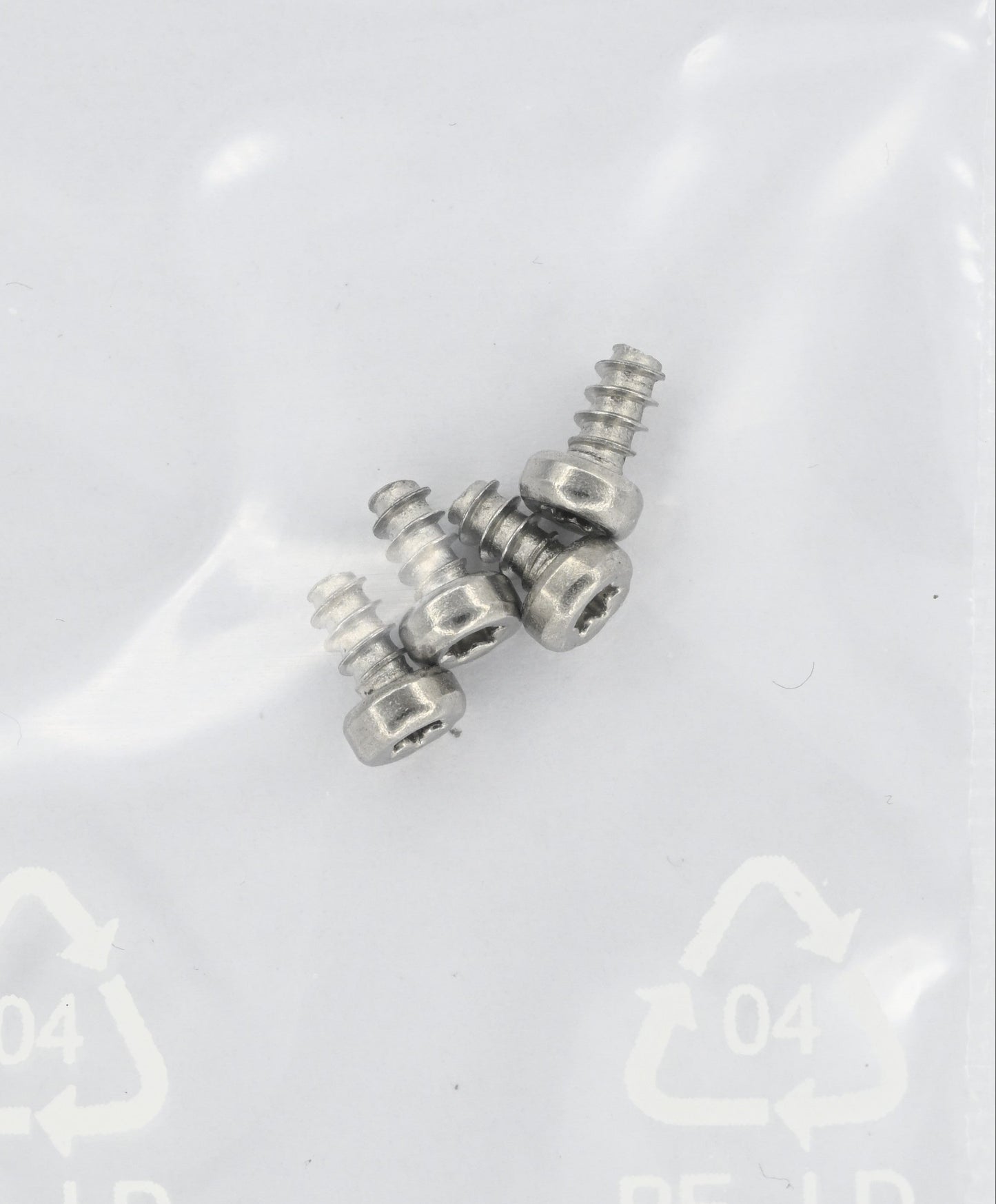
- 4× stainless steel A2 mounting screws, Ø 2.5 × 4.5 mm, T8 drive
- 1× solar connection cable, JST-PH 2.0 2-pin, 20 cm
- 1× BLE adhesive antenna 2.4 GHz, U.FL, 10 cm
- 1× battery cable, JST-PH 2.0 3-pin, 20 cm, in the chosen version (bare wire ends or with pre-soldered protection module)
Not included with any variant: battery, solar panel and 868 MHz LoRa antenna. 18650, 21700 or 26650 cells are the usual choice; matching solar panels are available in the shop. The BLE antenna covers only the 2.4 GHz service link, not the LoRa radio.
Firmware & software
The MR2 is currently supported by MeshCore only. Ready-made, tested MeshCore builds are available for download. Meshtastic support is planned, but no Meshtastic firmware for the MR2 exists yet. If your network runs on Meshtastic today, please check before purchasing whether MeshCore is an option for your use case.
The MR2 ships exclusively with the OTAFIX bootloader. No application firmware is pre-installed by design – you flash the firmware yourself. No programming adapter is required.
To flash, press the reset button twice in quick succession (double reset). The board then enumerates as a USB drive on your computer; copy the firmware onto it as a .uf2 file via drag and drop. After copying, the board restarts automatically.
Ready-made MeshCore builds for the MR2 are published as releases, currently Inhero MR2 v1.16.0 based on MeshCore v1.16.0. The releases contain three build variants – repeater, repeater with RS232 bridge, and sensor node – each as .uf2, .hex and .zip with SHA256 checksums, plus quick-start guides in German and English.
→ Firmware releases for the Inhero MR2
Inclusion of MR2 support in the official MeshCore project is being prepared. Until then, please use the builds linked above. As soon as Meshtastic support becomes available, we will announce it here and in the documentation.
Technical specifications
- Radio module: RAK4630 (nRF52840 + SX1262)
- MCU: nRF52840, ARM Cortex-M4, 64 MHz
- LoRa frequency range: 863.1–869.9 MHz
- Bluetooth Low Energy: 2.402–2.480 GHz (service mode only)
- Charge controller: BQ25798, buck/boost, MPPT, JEITA
- Solar input: 3.6–24 V, max. open-circuit voltage 25 V
- USB charging: 5 V via USB-C (shared input with solar)
- Charge current: 50–1500 mA, configurable via CLI
- Power monitor: INA228, coulomb counter, 100 mΩ shunt, max. 1.6 A
- Real-time clock: RV-3028-C7
- Environmental sensor: BME280 (temperature, humidity, barometric pressure)
- Step-down converter: TPS62840, 3.3 V, max. 750 mA
- Battery chemistries: Li-ion 1S, LiFePO₄ 1S, LTO 2S, Na-ion 1S
- Firmware support: MeshCore (available), Meshtastic (planned)
- Consumption in repeater operation: 12.3 mA at 3.3 V = 295 mAh/day = 0.98 Wh/day (24-hour measurement, typical radio traffic)
- Quiescent current, active idle: 6.0 mA at 4.2 V / 7.7 mA at 3.3 V
- Deep sleep: < 500 µA (charge path active, RTC wake-up)
- Interfaces: 2× U.FL, USB-C, solar, battery. (UART/I²C and SWD as solder pads on the rear)
- Dimensions: 45 × 40 mm
- Mounting: 4× M2.5 holes, 35 × 40 mm spacing
- Bootloader: Adafruit nRF52 OTA-Fix, UF2-capable
Delivery & shipping
- Shipping within Germany via DHL Paket (insured, with tracking)
- Delivery time: usually 2–4 business days
⚠ Important safety notes
- No reverse-polarity protection: The board has no hardware reverse-polarity protection on the battery or solar input. Reversed polarity causes immediate, irreversible damage. Always check polarity before connecting.
- Mind the cell chemistry: The cutoff thresholds of LiFePO₄ and Li-ion are not compatible. Choose the battery cable version to match your cell.
- NTC required: For Li-ion and LiFePO₄, an NTC must be connected or the solder jumper for the onboard NTC must be closed. Otherwise the charge controller blocks charging.
- No short circuit on the solar input while USB is connected: Both share the same input via a Schottky diode.
- LTO 2S: An external balancer is required for continuous operation; the board does not balance.
- ESD-sensitive assembly – handle only with appropriate ESD protection.
- Always connect an antenna when operating the LoRa/BLE transceivers.
Compliance (RED 2014/53/EU)
The hardware has been tested for conformity with the EU Radio Equipment Directive (RED 2014/53/EU) by an accredited test laboratory and is CE-compliant. The final transmission characteristics (transmit power, frequency, duty cycle) depend on the firmware installed by the user and the antenna chosen. The operator is responsible for configuring transmit power and antenna gain so that the applicable EU limits (EN 300 220, ERC/REC 70-03) are met.
Manufacturer (information pursuant to EU General Product Safety Regulation 2023/988)
Inhero GmbH, Gewerbestraße 19, 08115 Lichtentanne, Germany
Email: info@inhero.de
Product identification: Inhero MR2, hardware rev. 1.1